
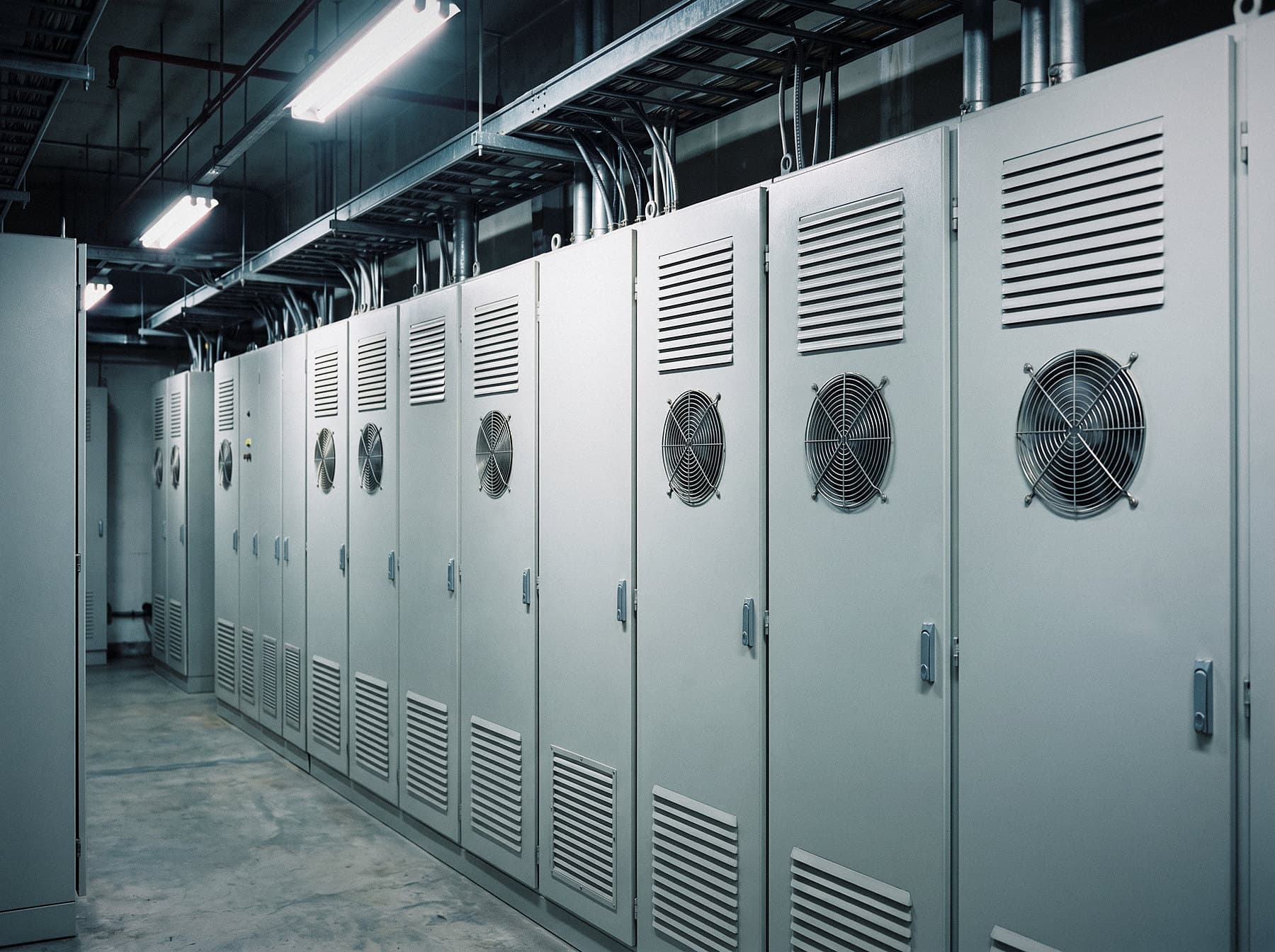
Electrical Equipment
Fan-cooled electrical equipment moves air through tight enclosures, past filters, heat sinks and louvers, and that cooling airflow is often the dominant noise source. The constraint is strict: a quieter design cannot run hotter.
Simulation-led aeroacoustics · Plymouth, Minnesota
Acoustic modeling and CFD for engine exhaust and intake silencers, generator-set enclosures, and machinery and equipment that moves air.
Solve aeroacoustics challenges early — before they become costly redesigns.
Firing-frequency tones sit low in the spectrum, where reactive silencer elements do most of the work; lined elements handle the broadband noise above them.
01Specialty
Engine and generator-set work is SH Consulting’s specialty. The same geometry is modeled for attenuation and for pressure drop, so a quieter silencer or enclosure still stays within the engine maker’s limits.
Transmission loss across the firing frequency and its harmonics, and the back pressure each design adds.
Air intakes, filters and intake silencers: attenuation, and restriction against the engine’s limit.
Enclosure levels against a site sound limit, louvers and splitter silencers, and ventilation and radiator airflow.
CFD of exhaust piping, rain caps and discharges: pressure drop and flow distribution.
02Why simulate early
Noise from engines and from equipment that moves air is set by geometry and operating point: silencer and enclosure layout, exhaust and duct routing, inlet conditions, openings and clearances. By the time it shows up on a prototype or in the field, most of those decisions are fixed — and the remaining options tend to be add-on treatment, extra cost and compromises in airflow.
Simulation brings the question forward. Predicting how flow and sound behave while the design can still change makes it possible to find the dominant sources, compare options on equal terms, and focus physical testing where it matters.
Estimate noise and airflow behavior before hardware exists.
Identify the mechanism behind the noise, not just the symptom.
Rank design options before committing to tooling or a prototype.
03Services
A specialist engineer on noise generated by moving air — from the first design question to a stubborn late-stage problem.
Predict how sound travels, resonates and radiates through a product or system — before it is built.
Predict back pressure, restriction and flow distribution through engine intakes, exhausts and silencers.
Understand the airflow through and around a design — pressure losses, velocities, separation and unsteadiness.
Identify the dominant source and path, understand the mechanism, and evaluate fixes before committing to them.
04Primary focus
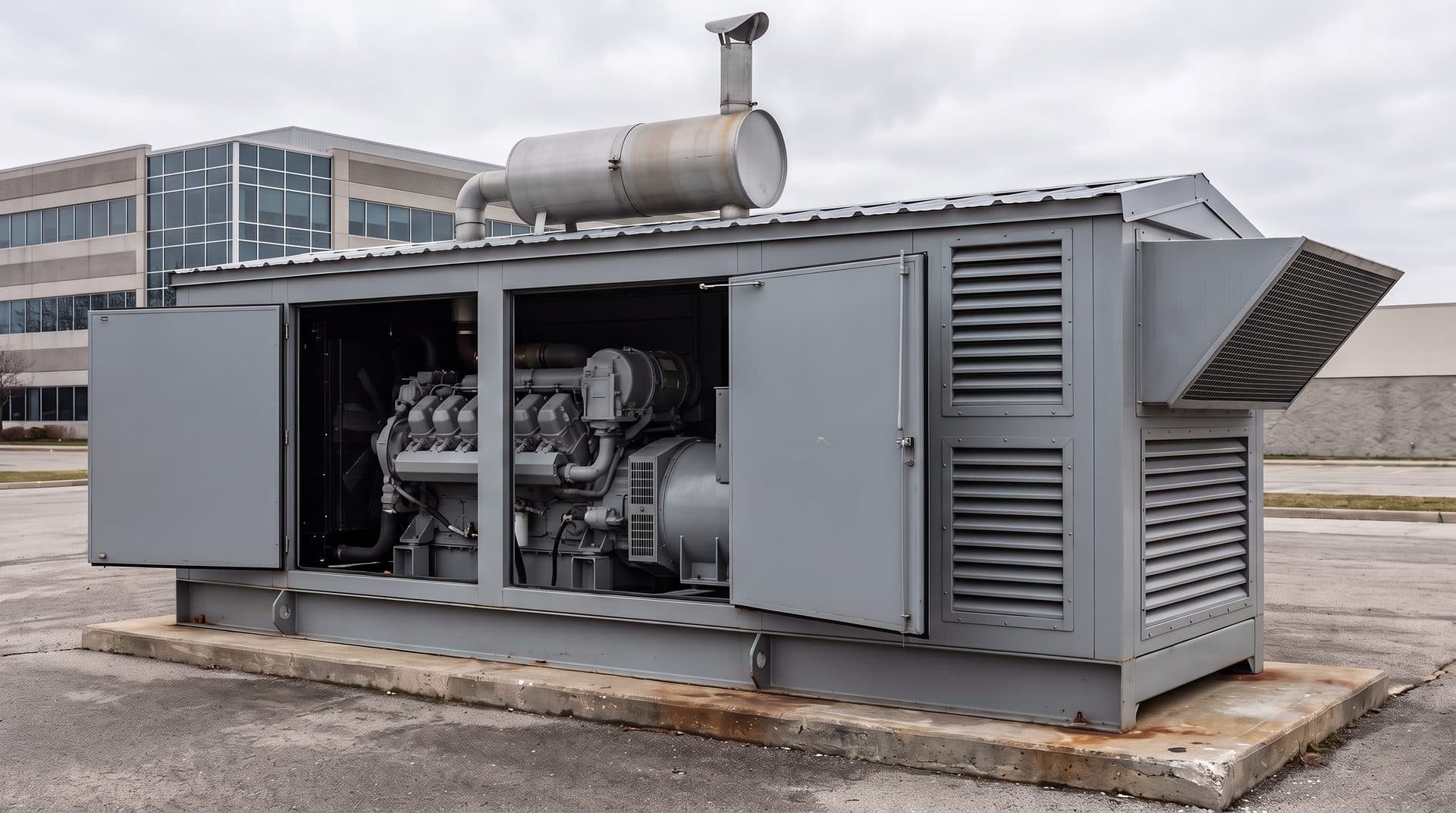
Generator sound mitigation and engine noise suppression are SH Consulting’s specialty. Exhaust and intake silencers, enclosures and ventilation paths are modeled for attenuation and for back pressure together, so the quieter design is one the engine can still run with.
Engine-driven generator sets pull large volumes of cooling and combustion air through sound-attenuated enclosures. The ventilation path has to pass that air with little restriction while keeping radiator-fan and engine noise inside.
Generator and engine noise simulation Generator sets in detail
05Industries
Fan-cooled electrical equipment moves air through tight enclosures, past filters, heat sinks and louvers, and that cooling airflow is often the dominant noise source. The constraint is strict: a quieter design cannot run hotter.
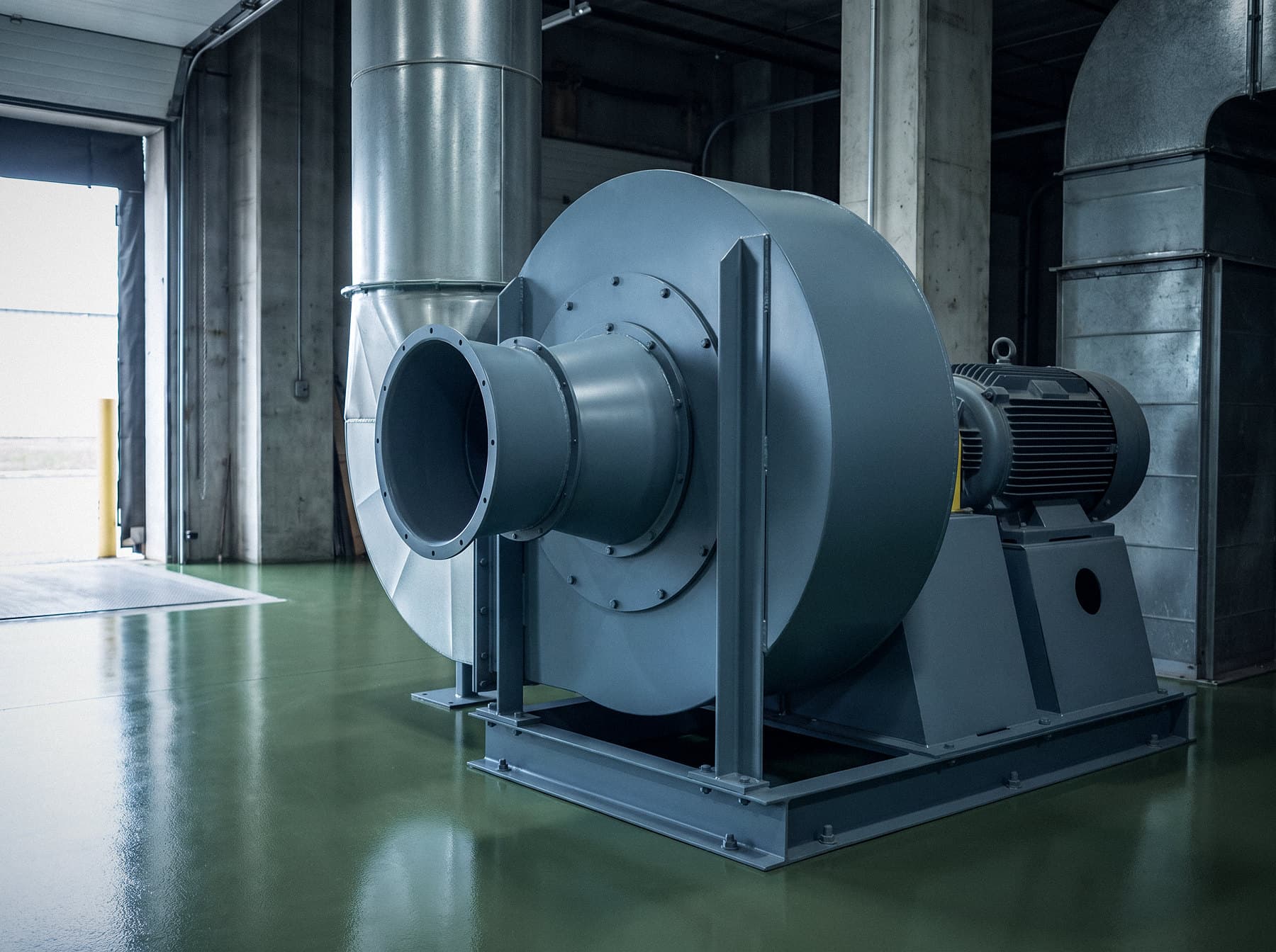
Industrial machines move air for cooling, combustion, conveying and ventilation, and that airflow is often one of the strongest noise sources on the machine. How the machine installs and packages its fans, ducts and openings decides much of what an operator hears.
Also: Fans & blowers · HVAC & data-center cooling · Engine & generator noise simulation
06Process
Every project starts with the engineering question — not with a software run. The level of analysis is matched to the decision, and results come back as specific recommendations.
What a simulation study needsThe product, the noise or flow behavior, the target, and the decision the work must support.
Prepare the geometry and operating conditions — or review an existing in-house model.
Run the acoustic, CFD or aerodynamic analysis the question actually requires.
Find which sources, paths and losses control the noise and the pressure drop.
Evaluate candidate changes on equal terms, for noise and for airflow.
Prioritized design changes, and where further simulation or testing is worth it.
07Experience
SH Consulting, Inc. brings 40+ years of aeroacoustics solutions to engineering teams. The firm is built around one specialty — how airflow generates noise, and how to engineer it out — applied through 3-D modeling and simulation.
Location
SH Consulting is based in Plymouth in the west Twin Cities metro and works with engineering teams across Minneapolis–Saint Paul and Minnesota.
Describe the product, the noise or flow behavior, and the decision you need to make. The first conversation is a technical one.